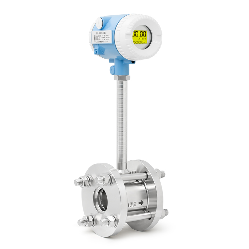
Installed the sensor horizontally, and the sensor with a nominal diameter of 10~40mm is connected with the pipeline; the sensor with a nominal diameter of 50~500mm is connected with the pipeline by a flange. The specific dimensions are shown in Table 2 and Figure 1. It is must ensured that the upstream side of the sensor is a straight pipe section with a length of not less than 20 times the diameter of the pipe, and the downstream side must have a straight pipe section with a length of not less than 5 times the diameter of the pipe. When the fluid is not clean, a filter should be installed on the upstream side of the sensor; when the liquid or fluid is mixed with gas, an air eliminator should be installed on the upstream side of the sensor. When the length of the straight pipe section on the upstream side cannot be guaranteed, a straightening (flow) device should be installed . During installation, another bypass line should be provided to facilitate cleaning and replacement.
In order to ensure the accurate measurement of the turbine flowmeter, the installation location and method must be correctly selected.
Requirements for straight pipe sections: The flowmeter must be installed horizontally on the pipeline (the inclination of the pipeline is within 5), the axis of the flowmeter should be concentric with the axis of the pipeline during installation, and the flow direction should be consistent. The length of the upstream pipeline of the flowmeter should have an equal diameter straight pipe section of not less than 2D. If the installation site is allowed, it is recommended that the upstream straight pipe section is 20D and the downstream is 5D.
Requirements for piping: The inner diameter of the upstream and downstream piping at the installation point of the flowmeter is the same as the inner diameter of the flowmeter.
Requirements for the bypass pipe: In order to ensure that the normal use of the medium is not affected when the flowmeter is overhauled, a cut-off valve (stop valve) should be installed on the front and rear pipes of the flowmeter, and a bypass pipe should be set at the same time. The flow control valve should be installed downstream of the flowmeter. When the flowmeter is in use, the shut-off valve installed upstream must be fully opened to avoid unstable flow in the upstream part of the fluid.
Requirements for the external environment: The flowmeter is best installed indoors. When it must be installed outdoors, sun protection, rain protection and lightning protection measures must be adopted to avoid affecting the service life.
Requirements for impurities contained in the medium: In order to ensure the service life of the flowmeter, a filter should be installed before the straight pipe section of the flowmeter.
Installation site: The flowmeter should be installed in a place that is easy to maintain and has no strong electromagnetic interference and heat radiation.
Requirements for installation and welding: the user shall provide a pair of standard flanges to be welded on the front and rear pipes. Welding with flow meter is not allowed! Before installing the flowmeter, the welding slag and other dirt in the pipeline should be strictly removed. To ensure that the flowmeter is not damaged during use. When installing the flowmeter, the gasket between the flanges must not be recessed into the pipeline.
Requirements for the grounding of the flowmeter: the flowmeter should be grounded reliably and cannot be shared with the ground wire of the strong current system.
Requirements for explosion-proof products: For the safe and normal use of the instrument, it is necessary to check whether the use environment of the explosion-proof flowmeter is in line with the user's explosion-proof requirements, and during the installation and use process, the national requirements for the use of explosion-proof products should be strictly observed, and users should not change it by themselves The connection method of the explosion-proof system must not open the instrument at will. The selection is within the specified flow range to prevent overspeed operation to ensure ideal accuracy and normal service life. Before installing the flowmeter, the debris in the pipeline should be cleaned: debris, welding slag, stones, dust, etc. It is recommended to install a filter with a 5-micron mesh upstream to block droplets and sand particles. When the flowmeter is put into operation, the front valve should be opened slowly first, and then the rear valve should be opened to prevent damage to the turbine due to instantaneous airflow impact. Lubricating oil should be operated according to the notice board, and the number of refueling depends on the cleanliness of the temperament, usually 2-3 times a year. Turbine overspeed due to pressure testing, purging of piping or exhaust, and turbine running in reverse flow can damage the flowmeter. When the flowmeter is running, it is not allowed to open the front and rear covers at will, and change the relevant internal parameters, otherwise it will affect the normal operation of the flowmeter. Install the gasket carefully, making sure that no protrusions enter the pipe to prevent interference with normal flow measurement. When the flowmeter is calibrated, the pressure should be collected at the pressure-taking port of the flowmeter.

 English
  français
  Deutsch
  Español
  italiano
  русский
  العربية


