Most Popular
The types of pressure sensors include sputtering film, silicon piezoresistance, strain gauges, sapphire, glass microfusion, ceramic piezoresistance, ceramic pressure capacitance, etc. The domestic mass production is mainly silicon piezoresistance, ceramic piezoresistance, glass microfusion and ceramics pressure capacity, the characteristics of these types of sensors are introduced below:
1. Silicon piezoresistance
Lefoo using the piezoresistive effect and good elasticity of semiconductor materials, a silicon piezoresistive sensor has been developed through integrated circuit technology and MEMS processing technology. At present, the minimum size of silicon piezoresistance can be within 0.5*0.5mm, so that on an 8-inch wafer Nearly 100,000 pressure sensors can be cut out. Silicon piezoresistive sensor, as a kind of micro sensor, has the advantages of small size, high output, low cost, strong overload ability, strong anti-interference ability, and high signal output sensitivity. Since the conventional package generally adopts a positive pressure structure, it can generally only measure some pure and non-corrosive media, and the temperature drift is relatively large, and the full-scale temperature drift can reach 0.15% F.S/℃.
At present, there are two commonly used packaging structures for silicon piezoresistive pressure cores: non-isolated and isolated. The non-isolated type is generally encapsulated in a plastic shell, and the surface of the silicon chip is protected by silicone gel. This structure is more suitable for automotive intake manifold pressure, The measurement of tire pressure and atmospheric pressure has obvious advantages in range and cost. It can also be used to measure the pressure of engine oil, water, and exhaust gas after packaging with special glue, but the service life problem is difficult to solve. Isolation packaging generally uses the internal oil filling method of the metal diaphragm. This packaging method can be used for corrosive or polluting media such as engine oil, refrigerant, fuel, exhaust gas, etc., but due to the complicated oil filling process, the production cost is high, compared to other types of sensors The price/performance ratio is not obvious.
In addition to the above two packaging methods, domestic pressure sensor manufacturer currently developing an inverted packaging structure. This structure directly contacts the dielectric from the back of the silicon wafer, which can avoid the risk of corrosion and pollution of the circuit on the surface of the silicon wafer. Once the inverted packaging process is mature, the silicon piezoresistive sensor will be suitable for more applications.
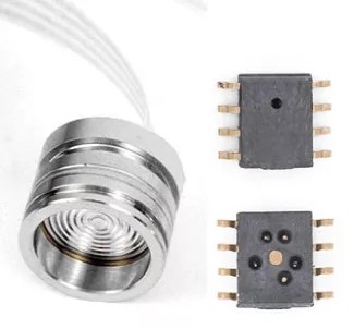
Figure 1-1 Diffused silicon pressure core
2. Ceramic piezoresistance
Ceramic resistor technology uses a thick film printing process to print the Wheatstone bridge on the surface of the ceramic structure, and uses the varistor effect to convert the pressure signal of the medium into a voltage signal. Ceramic is a recognized material with high elasticity, corrosion resistance, wear resistance, impact and vibration resistance.
The thermal stability of ceramics and its thick film resistance can make its operating temperature range as high as -40 to 135 ℃, and electrical insulation is 2kV. Such high insulation strength is difficult for other sensors to achieve. At present, many domestic manufacturers provide ceramics. Resistance pressure sensor core. However, the signal output sensitivity of this technology is low, the range is generally limited to 500kPa~10MPa, and the conventional hollow structure only depends on the pressure of the diaphragm, which has poor overload resistance. When the pressure of the medium to be measured is overloaded, the ceramic resistance sensor will have the diaphragm rupture. Risk of media leakage. Ceramic piezoresistance is suitable for pressure measurement applications of refrigerant, engine oil and brakes.
The ceramic piezoresistive sensor core has its own temperature compensation, and the temperature drift can achieve 0.02%F.s/℃, so for most applications, no temperature compensation is needed, which can reduce production costs. The time drift problem of general ceramic piezoresistive sensors is more prominent, which requires higher material procurement and production processes.
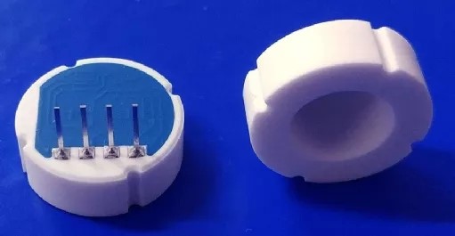
Figure 1-2 Ceramic piezoresistive core
3. Glass micro-melting
The glass micro-melting technology uses a high-temperature sintering process to combine a silicon strain gauge with a stainless steel structure. The four resistors equivalent to the silicon strain gauge form a Wheatstone bridge. When there is medium pressure on the other side of the stainless steel diaphragm, the stainless steel diaphragm produces a small deformation that causes the bridge to change, forming a voltage signal proportional to the pressure change. The glass micro-melting process is difficult to achieve and the cost is high. The main advantages are good medium tolerance and strong overload resistance. It is generally suitable for high pressure and ultra-high pressure ranges, such as 10MPa~200MPa, and its application is relatively limited.
Glass micro-melting pressure sensors have obvious advantages in high-pressure applications such as diesel common rail, loader hydraulics, and fuel pumps. For applications below 2MPa, there is no cost advantage. In addition, the temperature drift of the glass micro-melting pressure sensor is equivalent to that of the silicon piezoresistive sensor, and temperature compensation is required to achieve the required accuracy during calibration.
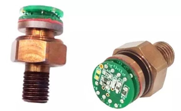
Figure 1-3 Glass micro-melt core
4. Ceramic pressure capacity:
The ceramic pressure-volume technology adopts a fixed ceramic base and a movable ceramic diaphragm structure, and the movable diaphragm is sealed and fixed with the base by means of glass slurry. Electrode patterns are printed on the inside between the two to form a variable capacitor. When the pressure of the medium on the diaphragm changes, the capacitance between the two changes. The signal is converted and conditioned by the conditioning chip and then output to the subsequent stage for use.
Ceramic pressure-capacitance technology has the advantages of wide range, good temperature characteristics, strong overload capability, and good long-term stability. It is widely used in pressure measurement of refrigerant, engine oil, brake, fuel, etc. Ceramic pressure-capacitance core has good temperature characteristics, for example, the temperature drift of 2MPa core is better than 0.5% F.s per 100°C. With JHM2102, only two-point calibration at room temperature is required, and the accuracy within 1.5% F.S in the temperature range of -40~125℃ can be achieved.
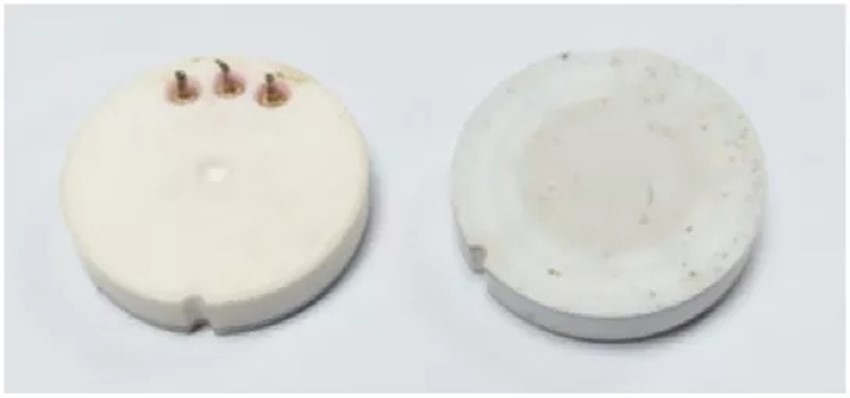
Figure 1-4 Ceramic pressure-capacitance core
The domestic ceramic pressure-capacitance technology is very mature. The production process of ceramic pressure-capacitance cores is simpler than that of piezoresistive cores, and the production cost is lower than piezoresistive. Now the prices of ceramic pressure-capacitance cores and ceramic piezoresistive cores have been flat. The inherent advantages of ceramic pressure capacity make it particularly suitable for high-reliability applications.
1. Features of JHM2102
JHM2102 is a signal conditioning integrated circuit designed for ceramic pressure-capacitance sensors. The ceramic pressure capacitance to be tested is generally composed of a variable capacitor and a reference capacitor, and the variable capacitor changes with the change of externally applied pressure. JHM2102 will measure the small changes of ceramic capacitors and convert them to analog voltage output after signal conditioning.
JHM2102 uses a compensation algorithm and circuit designed for ceramic pressure-capacitance cores. For most ceramic pressure-capacitance ranges, JHM2102 only needs two pressure point calibration at room temperature to achieve an accuracy of 1.5% F.S in the full temperature range.
The power supply voltage of JHM2102 is 4.5~5.5V, with ±40V overvoltage and reverse connection protection; ~4mA working current and -40~135℃ automotive-grade working temperature zone; using standard 3-wire communication, after simple calibration. It can output the required standard voltage signal; the JHM2102 external circuit only needs a few capacitors to work reliably, and there are reference circuits that can pass ISO11452-2, ISO11452-4, and ISO10605 standards.
2. Calibration principles of JHM2102
JHM2102 is a signal conditioning circuit designed for ceramic capacitance sensors. The ceramic capacitance sensor to which it is applied generally has two capacitances: a variable capacitance CVAR and a reference capacitance CREF, where CVAR changes with changes in external pressure, while CREF capacitance basically does not change with pressure changes. JHM2102 makes full use of the characteristics of these two capacitors, measures the ratio of the two, and produces a voltage signal output proportional to the pressure change after a series of signal conditioning.
After the JHM2102 is assembled with the ceramic capacitance sensor, it needs to be calibrated. The calibration needs to collect the voltage output under different pressure conditions at room temperature and calculate the accurate calibration parameters by external software. The externally connected circuit drives VDD to a specific voltage to enter the OTP programming mode. In this mode, the OUT pin becomes a digital input and output pin, and the external drive circuit writes the calculated calibration parameters into the OTP to complete the calibration.
3. Batch calibration kit
JHM2102 has a mature mass production kit, especially the MCB2100 calibration board can be directly installed on the automatic calibration test system, directly communicate with the industrial computer, and the calibration speed can reach 5S/piece. MCB2100 can also be used with 2100 batch calibration software to achieve manual calibration. For customers with low annual output, manual calibration can reduce equipment investment, and the calibration speed is slower, which can reach 45S/piece.
Customers can also achieve semi-automatic calibration by customizing fixtures and operating software, and the semi-automatic calibration speed can reach 15S/piece.
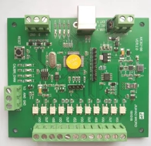
Figure 2-1 MCB2100 batch calibration board
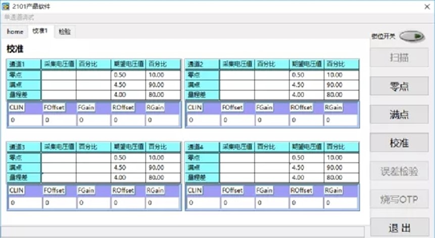
Figure 2-2 MC2100 batch calibration software
4. JHM2102 application circuit
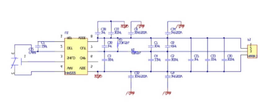
Figure 2-1 JHM2102 application circuit schematic diagram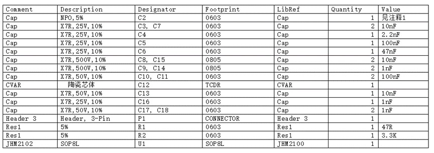
Table 2-1 JHM2102 application circuit BOM table
Note:
1. C2 is a reference capacitor, the capacitance value needs to be matched with the ceramic pressure-capacitance core, not a fixed value.
2. C8, C9, C14, and C15 are the capacitance of the sensor shell, and the withstand voltage and package should be selected according to the customer's requirements.
5. Advantages of JHM2102 program
The JHM2102 ceramic pressure-capacitance solution has been used in the automotive OEM market in batches, and the accuracy and reliability of the measurement have been recognized by customers.
It is well known that the capacitance variation of ceramic pressure capacity is reciprocal to the pressure, and the nonlinear is poor. The general capacitance pressure conditioning chip needs to collect multiple pressure points for fitting, in order to achieve the required accuracy. JHM2102 simplifies the calibration process by using an internal algorithm and a calibration circuit to calibrate a sensor with a nonlinear bias greater than 0.2%F.S by taking only two pressure points. JHM2102 internal circuit adopts temperature self-compensation technology, the chip temperature drift is very small, with low temperature drift ceramic capacitive core, can achieve normal temperature calibration to ensure the output accuracy of full temperature region within 1.5%. Greatly reduce the production cost of customers, improve the production efficiency. Using standard pressure controller and quick fixture, single person operation can calibrate more than 600 units per day (8-hour workdays).
Pre-inspection → assembly → high and low temperature aging → calibration → post-inspection → finished product
Before production, you need to prepare all the accessories of the sensor. These accessories include the sensor metal shell, gasket/ring, pressure-capacitance ceramic core, FPCB, connectors, sealant and other auxiliary materials.
1. Pre-inspectio
Tools used: calipers, FPCB test tooling
Check whether the dimensions of the metal shell and connectors meet the tolerance requirements of the drawings. Some plug-ins may change their dimensions due to heat, and need to be treated with high temperature aging in advance.
Check whether the size of the gasket (ring) meets the requirements of the drawing and whether the material is compatible with the customer's measuring medium.
Use FPCB test tooling to test whether FPCB is working properly.
Check whether the pressure-capacitance ceramic core meets the range requirements and whether the core is damaged.
2. Assembly
Tools used: constant temperature soldering station, press, stamping die
Use a constant temperature soldering station to weld the FPCB, connector and pressure-capacitance ceramic core together, place the sealing gasket in the groove of the sensor metal shell, install the ceramic pressure-capacitance core and connector into the metal shell, and connect The plug-in presses the ceramic pressure-capacitance core body to ensure the reliable grounding of the grounding shrapnel of the FPCB.
Use a press and a stamping die to rivet the metal shell and the connector (and assembly methods such as circlip and thread compression) together.
3. High and low temperature aging
Tools used: high and low temperature test chamber, sensor aging bracket
After the ceramic pressure-capacitance sensor is assembled, some products will have residual stress. If these stresses are not released, it may cause zero drift of the sensor.
High and low temperature aging is to place the assembled sensor at the lowest use temperature for a certain period of time, and keep it at the highest use temperature for a certain period of time, generally 3 cycles.
4. Calibration
Tools used: pressure controller, tooling and fixture (if automatic calibration is used, automatic calibration and inspection production line are required), JHM2102 batch kit
The calibration process of JHM2102 pressure-capacitance ceramic scheme has only a few simple steps:
Set desired output value→collect zero pressure data→collect full-scale pressure data→calculate calibration parameters→error check→write into OTP permanent storage.
5. Posterior
Tools used: pressure alternator, high and low temperature test chamber, pressure controller, tooling fixture, multimeter
Post-inspection can be random inspection or full inspection, and full inspection will increase production costs.
The pressure alternating test machine can test the sealing performance of the sensor and whether the residual stress is released completely.
Use pressure controllers, tooling fixtures, and high and low temperature test boxes to check whether the output accuracy of the sensors in the full temperature zone is within the allowable range.
Some products with high protection level need to be glued at the connection between the metal shell and the connector.
6. Some electrical performance tests for sensors
ISO11452-2, ISO11452-4, ISO10605, etc.
The anti-EMC reference circuit (FPCB) using JHM2102 can pass the 100V/m electromagnetic immunity test.
The JHM2102 ceramic solution can be calibrated by pneumatic pump manual pressurization in the debugging and small batch sample trial production stage. Manual pressurization is generally suitable for the output of 100 pcs/day or less. It is recommended to use a pressure controller for mass production, which can improve pressurization efficiency and reduce labor costs. The following are some recommended models of pressurized equipment:
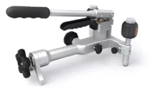
Manual pressure equipment: ConST118 (0~6MPa)
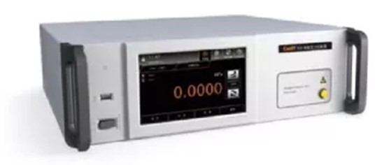
Pressure controller: ConST820 (0~6MPa)
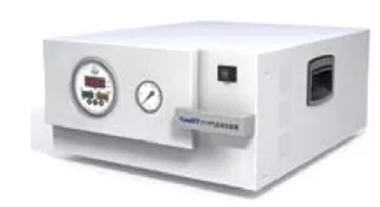
Air pressure generating device: ConST171S
 English
  français
  Deutsch
  Español
  italiano
  русский
  português
  العربية
  Türkçe
  Zulu
Zulu 

