Most Popular
(1) Influence of ambient temperature on zero drift of micro differential pressure transmitter
Place the micro differential pressure transmitter for test in the -10 ℃ high and low temperature incubator for 30 minutes, and start recording the output current of the micro differential pressure transmitter. Record the output current of the transmitter every 1 ℃ rise in the incubator temperature. The change of ambient temperature corresponds to the output current of micro differential pressure transmitter.
(2) Influence of power supply voltage on zero drift of micro differential pressure transmitter
According to the technical requirements provided in the transmitter manual, the output current of the micro differential pressure transmitter shall be recorded every 2VDC rise within the power supply voltage range of 18V-30VCD. The change of power supply voltage corresponds to the output current of micro differential pressure transmitter. It can be seen from the power supply voltage change experiment that the transmitter output is very stable within the rated voltage range of micro differential pressure transmitter.
(3) Influence of vibration on zero drift of micro differential pressure transmitter
In the constant temperature laboratory, install the micro differential pressure transmitter on the vibration test bench, and record the output current of the micro differential pressure transmitter after 8 hours of power on. Corresponding relationship between vibration and output current of micro differential pressure transmitter. Through the simulated field vibration experiment, it can be seen that the micro differential pressure transmitter is installed in the place with large vibration, which has an impact on its stability and produces large deviation.
(4) Influence of installation mode on zero drift of micro differential pressure transmitter
The H side of all micro differential pressure transmitters used for the test is located on the left side of the transmitter and the L side is located on the right side of the transmitter. Simulate the field installation with vertical 0°, left 45°, left 180°, right 45°, right 180°, front tilt 45°, front flat 180°, rear tilt 45° and rear flat 180° at a constant room temperature, and record the output current of the micro differential pressure transmitter after standing for 30 minutes. The installation mode corresponds to the output current of micro differential pressure transmitter.
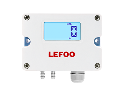
In Lefoo pressure transmitter manufacturers, From the experiments of the above four projects, it can be seen that the zero drift phenomenon of micro differential pressure transmitter and hvac differential pressure sensor under the influence of ambient temperature change, vibration and installation mode is impossible to avoid; The change of power supply voltage has little effect on the stability of micro differential pressure transmitter.
According to the experimental results, combined with the actual use conditions on site, the instrument worker can take the following measures to improve the zero drift of the micro differential pressure transmitter when there is no way to change the inherent stability of the micro differential pressure transmitter.
(1) When the micro differential pressure transmitter is selected to measure the medium flow together with the transport pipe, the measurement error caused by the zero drift of the micro differential pressure transmitter may be too large for the user to accept. If it can be replaced by other measurement methods, it shall be replaced as far as possible to ensure the accuracy of flow measurement results.
If the micro differential pressure transmitter must be selected to measure the flow, the flow range shall not be placed near the lower range of the micro differential pressure transmitter as far as possible, and the working range shall preferably be within 1/3 ~ 1/2 of the upper range of the micro differential pressure transmitter, so as to ensure that the accuracy of the whole set of differential pressure flowmeter can meet the use requirements.
(2) When installing the micro differential pressure transmitter on site, the construction shall be standardized to avoid vibration and inclined installation as far as possible. The ambient temperature of the micro differential pressure transmitter is better in the area with relatively stable temperature to minimize the impact of external factors on the zero drift of the micro differential pressure transmitter.
(3) Do well in the selection of micro differential pressure transmitter, and try to select micro differential pressure transmitter with good stability when funds allow, so as to fundamentally reduce the measurement trouble caused by zero drift of micro differential pressure transmitter and the maintenance workload of instrument workers.
MORE_RELATED_PRODUCTS


 English
  français
  Deutsch
  Español
  italiano
  русский
  português
  العربية
  Türkçe
  Zulu
Zulu 